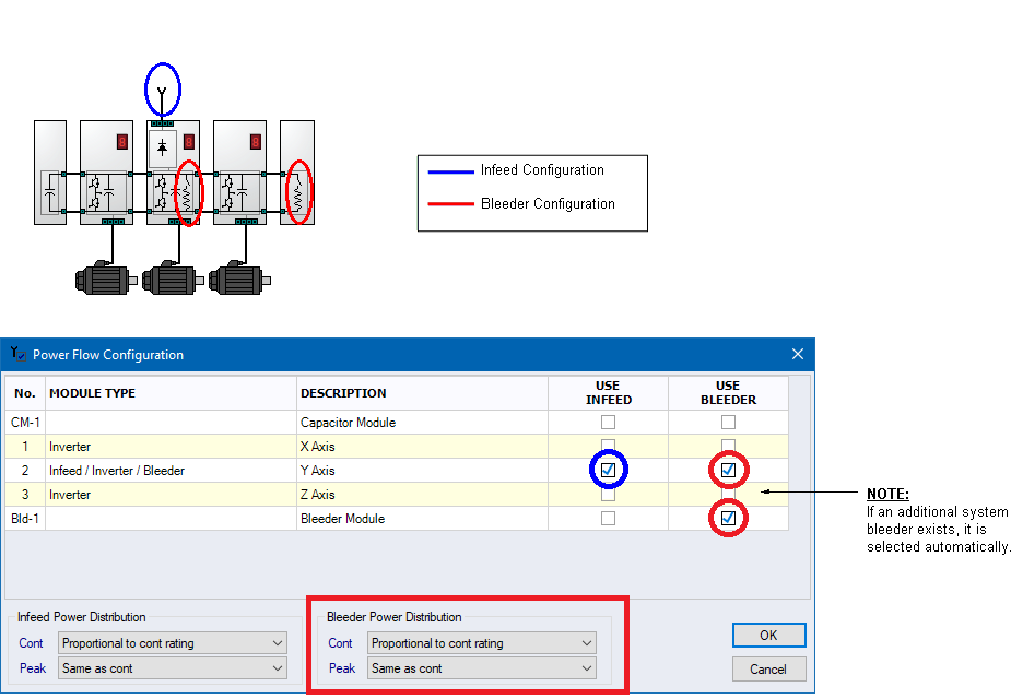
Sample 1 - Power Flow Configuration |
When there is more than one bleeder, the user has the option to specify if the total bleeder power is:
1. Divided equally among all bleedersExample2. Divided proportionally to each bleeder’s continuous power rating
If the total required braking power, PTotal = 1000W and there are n = 2 bleeders
Then the continuous power through each bleeder is:
P1 = P2 = PTotal / n = 1000 / 2 = 500W
3. Divided proportionally to resistor current. Ie. All choppers are synchronized such that they engage and disengage simultaneously.Example
If the total required braking power, PTotal = 1000W, P1Rating = 250W and P2Rating = 1000W
Then the continuous power through each bleeder is:
P1 = PTotal x P1Rating / (P1Rating + P2Rating) = 1000 x 250 / (250 + 1000) = 200W
P2 = PTotal x P2Rating / (P1Rating + P2Rating) = 1000 x 1000 / (250 + 1000) = 800W
Example
If the total required braking power, PTotal = 1000W, R1 = 50 Ohms and R2 = 10 Ohms
Then the continuous power through each bleeder is:
P1 = PTotal x 1/R1 / (1/R1 + 1/R2) = 1000 x 1/50 / (1/50 + 1/10) = 167W
P2 = PTotal x 1/R2 / (1/R1 + 1/R2) = 1000 x 1/10 / (1/50 + 1/10) = 833W