Die Kommandozeilenschnittstelle (CLI) ist eine Option zur PRO
Version, die es einem externen Optimierungstool erlaubt, SERVOsoft®
zu steuern und die Sequenz Auto Update Funktion zu
nutzen. Das externe Programm kann ein Profilgenerator, oder
typischerweise ein Optimierungstool (OT), sein, das die Sequenz mit
jeder Iteration anpasst. Die Sequenzen können gestaltet sein wie
jede, die im Programm erzeugt werden kann, einschließlich
Kurvenprofile, Polynome und Splines sowie mit dynamischen Last- und
Schubprofilen.
Ein OT steuert SERVOsoft® über die CLI. Wenn SERVOsoft® im
CLI-Modus gestartet wird, öffnet es eine spezielle Projektdatei und
startet die Funktion Sequence Auto Update für die
angegegebene Slot-Nummer. Dann beginnt SERVOsoft® den ständigen
Ablauf von Lesen, Berechnen und Ausgeben eines XML-Reports für jede
neue Achssequenz (Seq.txt) die vom OT im „Arbeitsverzeichnis“
bereitgestellt wird. Wenn das OT fertig ist, übergibt es eine
letzte Datei mit einer „Fertig“-Sequenz. Daraufhin wird SERVOsoft®
beendet.
Die CLI benutzt ein Trennzeichen „|“ in der Weise:
SERVOsoft.exe
KommandoTyp|Sichtbarkeit|ProjektDatei|Arbeitsverzeichnis|Betriebsmodus|[SlotNummer]
- KommandoTyp
- Wert: 100
- Ein Integer, das den aktuellen Typ der Schnittstelle
angibt
- Kann in Zukunft bei Änderungen in der Schnittstelle mit
weiteren Werten ergänzt werden
- Sichtbarkeit
- Werte:
- 0 (minimiert)
- 1 (sichtbar)
- Gibt an, ob das Programm minimiert [0] oder sichtbar [1]
läuft
- Kann für die Analyse oder Fehlersuche genutzt werden. Für
schnellere Bearbeitung sollte das Programm minimiert laufen, da
dann die Bedienoberfläche nicht aufgerufen werden muss.
- ProjektDatei
- Voller Pfad und Dateiname der SERVOsoft® [.ssp4]
Porjektdatei
- ArbeitsVerzeichnis
- Gibt an, wo die „Seq.txt“-Datei liegt
- Z.B. “C:\WorkingFolder\Seq.txt”
- Das Ergbenis wird gespeichert unter
“C:\WorkingFolder\Results”
- Betriebsmodus
- Werte:
- 0 (Normal)
- 1 (Max-Stop)
- 2 (Notstrom)
- [SlotNummer]
- Werte: 1, 2, … bis zur Slotnummer des letzten
Antriebsmechanismus in der Projektdatei
- Gibt an, welcher Slot bzw. Achse bearbeitet werden soll
- Wenn nichts angegeben ist, wird standardmäßig die erste
Antriebsachse im Projekt verwendet
Das Format der Seq.txt Datei wird vom Benutzer in der
Achsen-Sequenz des Projektes festgelegt wie beschrieben unter
Sequenz Auto Update.
Um den Prozess zu beenden, sollte die letzte Seq.txt-Datei die
Zeile "Done" enthalten und optional den Parameter {SaveProjectAs}.
Um die Berechnung an einer anderen Achse im selben Projekt
fortzuetzen, muss die Seq.txt-Datei den Parameter {NextSlotNumber}
enthalten.
Die Syntax ist folgende:
Done
{SaveProjectAs= PfadundDateiname}
{NextSlotNumber= X}
wobei die {}-Klammern einen optionalen Parameter anzeigen
{SaveProjectAs=PfadundDateiname}
- Speichern des Projektes unter dem angegebenen Pfad und
Dateinamen.
- Diese Option bietet die Möglichkeit, das Projekt an anderer
Stelle zu speichern als dem aktuellen Projektpfad.
- Anmerkung: Wenn der Prozess "Done" ist, wird das Projekt
automatisch mit dem aktuellen Dateinamen im aktuellen Projektpfad
gespeichert.
{NextSlotNumber=X}
- X ist die nächste Slot-Nummer
- X muss eine gültige Slot-Nummer zwischen 1 und der maximalen
Anzahl Achsen im Projekt sein, und der Typ des Slots muss
"Antriebsmechanismen" sein und kein Modul wie Einspeisung, Bleeder
etc.
Wenn Sie zum Beispiel nach der Bearbeitung von Achse 1 mit Achse
2 weitermachen möchten, sieht das in der Datei Seq.txt so aus:
Done
NextSlotNumber= 2
Wenn Sie danach das Projekt speichern und dann z.B. zurück zu
Achse 1 gehen möchten, schreiben Sie in die Date Seq.txt:
Done
SaveProjectAs= C:\Project ABC\Scenario 5\Test3.ssp4
NextSlotNumber= 1
Wenn {NextSlotNumber} nicht geändert wird, bleibt das Programm
in der Bearbeitung der aktuellen Slot-Nummer und wartet auf die
nächste Seq.txt.
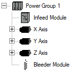
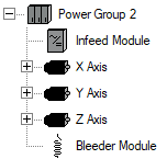
Die Slotnummer ist spezifisch für eine Achse bzw. ein Modul in
einem Projekt. Wenn z.B. ein Projekt zwei Leistungsgruppen enthält,
jede mit einem Einspeise- (Inf) und einem Bremsmodul (Bld) sowei
drei Achsen (X, Y, Z), dann sind das fünf Slots je Leistungsgruppe
(PG). Die zehn Slotnummern sind dann:
| Baumansicht |
Slot |
Abkürzung |
Typ |
|
- |
PG1 |
Leistungsgruppe |
| 1 |
PG1.Inf1 |
Einspeise-Modul |
| 2 |
PG1.Ax1 |
Achse |
| 3 |
PG1.Ax2 |
Achse |
| 4 |
PG1.Ax3 |
Achse |
| 5 |
PG1.Bld1 |
Bleeder-Modul |
|
- |
PG2 |
Leistungsgruppe |
| 6 |
PG2.Inf1 |
Einspeise-Modul |
| 7 |
PG2.Ax1 |
Achse |
| 8 |
PG2.Ax2 |
Achse |
| 9 |
PG2.Ax3 |
Achse |
| 10 |
PG2.Bld1 |
Bleeder-Modul |
In diesem Beispiel sind die Slots 2 - 4 und 7 - 9 gültig für die
Kommandozeilenschnittstelle, weil sie Antriebsmechanismen sind,
auch als „Achse“ bezeichnet, während die Slots 1, 5, 6 und 10
"Einspeisemodul" und "Bremsmodul"-Slots sind. Ein "Modul"-Slot kann
ein Einspeise-, Brems-, Kondensator- oder Energiespeichermodul
(ESM) sein. Obwohl der XML-Report Auslastungsdaten dieser Module
enthält, sind das keine sequenzbasierenden Achsen und können
deshalb nicht in einer seq.txt-Datei angesprochen werden.
Verwandte Themen
 Funktionsbeschreibung