Bleeder Module |
A Bleeder Module removes excess energy from the bus and dissipates it as heat. A Bleeder Module consists of a Chopper and Resistor as shown in the graphic below.
![]()
|
When using a bleeder module, always check that it is compatible with the connected device. To do this, check the manuals and data sheets of both devices – even when there is no message in the System Check. |
|
 How a Bleeder
Works & Bleeder Types
How a Bleeder
Works & Bleeder Types
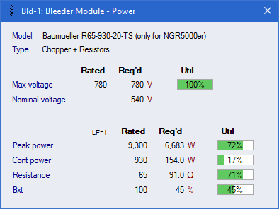
When a motor is braking and its Inverter is in regenerative mode, the bus voltage rises to store the braking energy. If the bus voltage rises to its threshold voltage, the Chopper engages to bleed excess energy through the Resistor to ensure the bus voltage does not exceed the threshold voltage.
Two Bleeder types are defined in the database, "Typ 0 = Chopper + Resistors" and "Typ 1 = Resistors Only". "Typ 0 = Chopper + Resistors" connect directly to the DC bus. "Typ 1 = Resistors Only" are for those Drives and Infeed Modules that have an Internal Chopper that connects to an External Resistor.
Power flow to the resistor is reduced proportionally by the chopper efficiency.
 Main Form
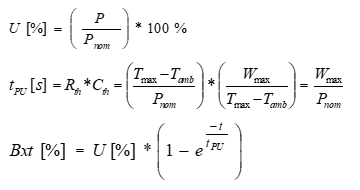
Bleeder
Calculations
Main Form
Bleeder
Calculations