Cable DC Bus
|
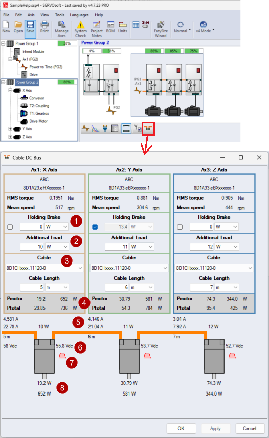
Size the DC Bus cables for remote Drive-Motors, aka Motor Integrated Drives (MiDs), located around the machine, connected by suitable cables in a daisy chain arrangement.
Cables can be selected in the Cable DC Bus form, launched from the Main form as shown.
This example shows Power Group 1, mounted in a cabinet, with an Auxiliary Power Module (APM) in Slot 2, stepping down the DC Bus from 540Vdc to 58Vdc to feed Power Group 2.
The cable length is an important factor in sizing the cables, as the total cable length of the daisy chain can result in signficant voltagen dips further down the chain. Additional loads such as remote I/O and/or the motor holding brake can be added.
|
|
Enable the motor's brake power consumption or enter your own value |
||||||
|
|
Specify additional loads such as remote I/O connected to the Drive. |
||||||
|
|
Select from a list of cables from the and specify the cable length. Listed cables are specific to the Drive's Vendor. In the database cables are defined by resistance per length, with or without connectors and their resistance, among other parameters. |
||||||
|
|
|
||||||
|
|
Cont Current RMS [Icont] and Max Current [Imax] |
||||||
|
|
Minimum voltage [Vz,min] at the drive | ||||||
|
|
Launch the Cable DC Bus Sequence Chart to view important profiles for DC Bus cables including the bus voltage seen at the motor, cable power and current, etc. |
||||||
|
|
Motor Cont (avg) Power [Pcont] and Max Power [Pmax] at the motor shaft. Ie. mechanical power |