The CAM Rotary mechanism models a CAM Driven Rotary table. The
CAM is defined in a table that can be defined manually or imported
from another tool. The CAM Efficiency can be defined as a formula
based on the CAM & Table angle, speed and max speed.
| The 'CAM Rotary' feature is available with
the PRO version |
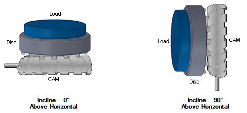
Unbalanced Load and Incline Angle
Motion profile position, b
= 90°
(CAM underneath Table, not shown)2
|

Incline, q = 0°
Above Horizontal
Side View
|

Incline, q =
90°
Above Horizontal
Side View
|

The CAM Efficiency Formula allows for the CAM efficiency based
on the variables Input Speed [n] and Output Torque [T]. The formula
can be up to 500 characters, and can use any of the following:
| Formula Variables
|
Units
|
| xCam |
CAM Angle |
°, rad, rev |
| wCam |
CAM Velocity |
°/s, rad/s, rev/s |
| wMaxCam |
CAM Max Velocity |
°/s, rad/s, rev/s |
| xTbl |
Table Angle |
°, rad, rev |
| wTbl |
Table Velocity |
°/s, rad/s, rev/s |
| wMaxTbl |
Table Max Velocity |
°/s, rad/s, rev/s |
| |
| Constants
|
| PI |
Pi (3.14159265358979...) |
| |
| Arithmetic
|
| + |
Addition |
| - |
Subtraction |
| * |
Multiplication |
| / |
Division |
| \ |
Integer division |
| ^ |
Exponentiation (raise to a power of) |
| Mod |
Modulus arithmetic
| |
5 Mod 2 |
= |
1 |
| |
5 Mod -2 |
= |
1 |
| |
-5 Mod -2 |
= |
1 |
| |
-5 Mod 2 |
= |
-1 |
| |
Abs(-5 Mod 2) |
= |
1 |
|
| When multiplication and division occur together in
an expression, each operation is evaluated as it occurs from left
to right. Likewise, when addition and subtraction occur together in
an expression, each operation is evaluated in order of appearance
from left to right. |
| |
| Comparison
|
| = |
Equality |
| <> |
Inequality |
| < |
Less than |
| > |
Greater than |
| <= |
Less than or equal to |
| >= |
Greater than or equal to |
| Is |
Object equivalence |
|
When the comparison is True, the result value is
1. Eg. (3>2)=1
When the comparison is False, the result value is
0. Eg. (1>2)=0
|
| |
| Math Functions
|
Units
|
| Abs |
Absolute
Eg. Abs(-1)=1 |
|
| Atn |
Arctangent
Eg. Atn(1)=PI/4 |
|
| Cos |
Cosine of an angle
Eg. Cos(PI/4)=0.707106781... |
[rad] |
| Exp |
e raised to a power
Eg. Exp(1)=e=2.718281828459... |
|
| Log |
Natural logarithm
Can be combined to create the Log of any base, n.
Eg. Logn(x) = Log(x) / Log(n) |
|
| Sgn |
Sign of a number
x>0: Sgn(x)=1, x=0: Sgn(x)=0, x<0: Sgn(x)=-1 |
|
| Sin |
Sine of an angle
Eg. Sin(PI/4)=0.707106781... |
[rad] |
| Sqr |
Square root
Eg. Sqr(9)=9^½=3 |
|
| Tan |
Tangent of an angle
Eg. Tan(PI/4)=1 |
[rad] |
| Int |
Integer portion of a number1 |
|
| Fix |
Integer portion of a number1 |
|
| 1The difference between Int and Fix is
that if number is negative, Int returns the first negative integer
less than or equal to number, whereas Fix returns the first
negative integer greater than or equal to number. For example, Int
converts -8.4 to -9, and Fix converts -8.4 to -8. |
| |
| Logical
|
| And |
Logical conjunction |
| Not |
Logical negation |
| Or |
Logical disjunction |
| Xor |
Logical exclusion |
| Eqv |
Logical equivalence |
| Imp |
Logical implication |
| |
| Derived Math Functions
|
| Secant |
Sec(X) = 1 / Cos(X) |
| Cosecant |
Cosec(X) = 1 / Sin(X) |
| Cotangent |
Cotan(X) = 1 / Tan(X) |
| Inverse Sine |
Arcsin(X) = Atn(X / Sqr(-X * X + 1)) |
| Inverse Cosine |
Arccos(X) = Atn(-X / Sqr(-X * X + 1)) + 2 * Atn(1) |
| Inverse Secant |
Arcsec(X) = 2 * Atn(1) – Atn(Sgn(X) / Sqr(X * X – 1)) |
| Inverse Cosecant |
Arccosec(X) = Atn(Sgn(X) / Sqr(X * X – 1)) |
| Inverse Cotangent |
Arccotan(X) = 2 * Atn(1) - Atn(X) |
| Hyperbolic Sine |
HSin(X) = (Exp(X) – Exp(-X)) / 2 |
| Hyperbolic Cosine |
HCos(X) = (Exp(X) + Exp(-X)) / 2 |
| Hyperbolic Tangent |
HTan(X) = (Exp(X) – Exp(-X)) / (Exp(X) + Exp(-X)) |
| Hyperbolic Secant |
HSec(X) = 2 / (Exp(X) + Exp(-X)) |
| Hyperbolic Cosecant |
HCosec(X) = 2 / (Exp(X) – Exp(-X)) |
| Hyperbolic Cotangent |
HCotan(X) = (Exp(X) + Exp(-X)) / (Exp(X) – Exp(-X)) |
| Inverse Hyperbolic Sine |
HArcsin(X) = Log(X + Sqr(X * X + 1)) |
| Inverse Hyperbolic Cosine |
HArccos(X) = Log(X + Sqr(X * X – 1)) |
| Inverse Hyperbolic Tangent |
HArctan(X) = Log((1 + X) / (1 – X)) / 2 |
| Inverse Hyperbolic Secant |
HArcsec(X) = Log((Sqr(-X * X + 1) + 1) / X) |
| Inverse Hyperbolic Cosecant |
HArccosec(X) = Log((Sgn(X) * Sqr(X * X + 1) + 1) / X) |
| Inverse Hyperbolic Cotangent |
HArccotan(X) = Log((X + 1) / (X – 1)) / 2 |
| Logarithm to base N |
LogN(X) = Log(X) / Log(N) |
Notes
1) Per the above formulae, the Disc Mass, MDisc, and
Load Mass, MLoad, are only used for the Torque due to
friction, Tm,
and only have an effect when the incline angle, q <> 90o
2) As a general rule, the CAM should be underneath the table so
oil properly lubricates the CAM via gravity.
| Symbol |
Description |
Units |
| JDM |
Inertia of drive mechanism |
kg-m2 |
| JCam |
Inertia of CAM |
kg-m2 |
| JDisc |
Inertia of disc |
kg-m2 |
| JLoad |
Inertia of load + payload |
kg-m2 |
| TDM |
Torque of drive mechanism |
Nm |
| TThrust |
Thrust torque at load |
Nm |
| Tv |
Torque vector at load |
Nm |
| Tm |
Torque due to friction |
Nm |
| TUL |
Torque due to unbalanced load |
Nm |
| aCam
|
CAM rotational acceleration |
rad/s2 |
| aTbl
|
Table rotational acceleration |
rad/s2 |
| iCam |
CAM ratio |
:1 |
| h
|
CAM efficiency |
1 |
| b
|
Motion profile position |
o
|
| q
|
Incline angle above horizontal |
o
|
| mDisc
|
Disc friction coefficient |
|
| MDM |
Mass of drive mechanism |
kg |
| MDisc |
Mass of disc |
kg |
| MLoad |
Mass of load |
kg |
| MUL |
Mass of unbalanced load |
kg |
| rUL |
Offset radius of unbalanced load |
m |
| g |
Acceleration due to gravity = 9.81 |
m/s2 |
| Fr |
Radial force |
N |
| Fa |
Axial force |
N |
Related topics
 CAM Efficiency Formula