Guidelines for Sizing Cables, Filters and Fuses |
Typically, sizing components at the infeed supply begins with calculating the RMS current and peak current at the infeed supply. This section of the help file explains how to use the program results to calculate the RMS and peak current. However, it is strongly recommended to consult the vendor's documentation for each vendors' specific sizing method.
The power factor at the infeed supply is not calculated by the program. It is a function of the infeed module and its power load, if a choke is connected or not, and if connected, the specific details of the choke. This is the reason the program only calculates the real power values. Typically, Infeed/Regen modules with a controlled bus, usually have a power factor of 1 when used with its proper choke. However, Infeed modules with an unregulated bus can have a wide range of power factors.
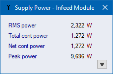
The infeed supply power is broken down in detail as shown below. The continuous (or average power) is shown for understanding power flow and efficiency. It is also helpful in understanding the relationship between continuous and peak power. The continuous power is typically not used for sizing cables, filters and fuses. Instead, the RMS power is used to calculate the RMS current at the infeed supply. The peak power value is used to calculate the peak current. Again, note that the unknown variable is the power factor, which must be estimated based on the vendor's documentation.
Sample Calculation for RMS
Current (IRMS) and Peak Current
(IPeak) at the Infeed Supply
Consider the following conditions:
IRMS= PRMS / (Sqrt(3) x V x PF50%= 2322 / (Sqrt(3) x 400 x 0.9) = 3.72A
IPeak= PPeak / (Sqrt(3) x V x PFPeak= 9696 / (Sqrt(3) x 400 x 0.7) = 20.0A