Kinetic Buffer |
|
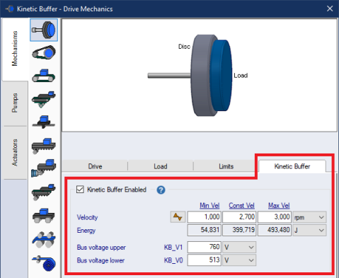
A Kinetic Buffer (KB) axis is used to store energy mechanically in a rotating disc, also known as a Flywheel. This energy can be used in a mains power loss to feed the DC bus with energy for a machine to finish its cycle and come to a controlled stop. During a mains power loss, the KB can also be used to absorb energy in a rapid braking event. Enable the KB feature in the Rotary mechanism form. When the KB feature is enabled, the axis sequence is a locked down and cannot be changed in the Sequence form unless the KB feature is turned off. In Normal mode, the KB maintains its Constant Velocity [Const Vel]. In Backup Power mode, during the mains power loss, the KB is engaged to maintain the DC bus within KB_V0 and KB_V1. If the KB velocity drops below its Minimum Velocity [Min Vel], or rises above its Maximum Velocity [Max Vel], then a System Check warning message occurs. The Min Vel Is used as a warning, as the KB can still drop to 0. However, the Max Vel is the maximum allowed, such that when adding energy to the flywheel, the KB absorbs energy up to its MaxVel. And when MaxVel is reached, then the regen energy will accumulate on the DC bus and then eventually overflow to the Bleeder. When the power loss ends, the Recovery ramp is used to ramp the KB to its Const Vel. When in Max-Stop mode, the KB maintains its Constant Velocity. The KB is assumed to be in its own protected cage and always runs at its set speed until a power loss triggers it to be used for backup power management. In Master Follower applications, when in Normal Operating Mode, the KB axis maintains its Constant Velocity regardless of any changes to the Master. The only time the KB velocity changes from is in Backup Power Mode during the loss of mains supply power.
|
|