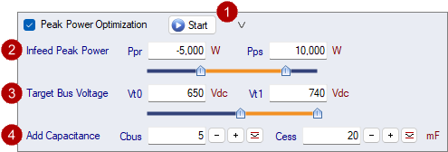
Supply Peak Power Optimization minimizes the Supply Peak Power
in Shared Bus applications by finding the best balance of energy
storage while optimizing four parameters - Infeed Peak Power Supply
[Pps] and Regen [Ppr] limits, and the Target Bus Lower and Upper
Voltages [Vt0, Vt1]. In the ideal case, the Supply Peak Power
[Pmax] is reduced to a low constant power over the entire
cycle.
| 'Supply Peak Power Optimization' is available
in the PRO version. |
|
This feature requires:
|
Active Infeed
- Controlled DC Bus voltage (ie. active Infeed, not passive)
- Programmable DC Bus Target Lower [Vt0] and Upper [Vt1]
voltages
- Programmable DC Bus Nominal [Vz0] and Threshold [Vz1]
voltages
- Programmable Peak Power Limit for Supply [Pps] and Regen
[Ppr]
Passive Infeed
- A "Peak Power Shaving Module" to react to and limit the Mains
Supply current.
- A Passive Infeed cannot target a bus voltage. Therefore, set
Vt0=Vz0 and Vt1=Vz1, and no Regen Power Limit.
|
|

|
[Start]: Find Lowest Peak Power using [Pps], [Ppr],
[Vt0] and [Vt1]
Click the [Start] button to find the lowest peak power by
adjusting the four variables [Pps], [Ppr], [Vt0] and [Vt1].
Depending on the application, up to 3 solutions may be
found:
1) Lowest Peak Power
2) Lowest Peak Power No Regen
3) Lowest Const Peak Power
Note: This function uses [Cz] and [Cess] as specified, but does
not change them.
|
|

|
Infeed Peak Power Limit for Supply [Pps] and Regen
[Ppr]
Use the Infeed Peak Power Supply [Pps] and Regen [Ppr] limits to
throttle the power flow to/from the DC bus to reduce the Peak Power
to/from the Mains Supply.
If the application requires more power than can be delivered by
the combination of the peak power limit(s), DC Bus and ESS (if
available), then the peak power limit(s) will be exceeded to meet
the application demand. As such, enough DC Bus and/or ESS energy
storage is essential to manage and reduce the Infeed Peak
Power.
|
|

|
Target Bus Voltages [Vt0, Vt1]
Increasing the Target Bus Lower Voltage [Vt0] increases the
amount of energy stored on the DC bus that can be used to feed the
application when the supply is limited. This can reduce the
on-demand peak power from the Mains Supply. Decreasing the Target
Bus Upper Voltage [Vt1] leaves energy storage room on the DC Bus to
absorb braking energy. This can reduce the regen power fed back to
the Mains Supply. Depending on the application, increasing Vt0 may
push more energy to regen or braking via a bleeder. But in certain
applications, it can be very advantageous to operate at Vt0 >
Vz0.
|
Voltage levels are limited per the following:
Vz0 <= Vt0 <= Vt1 <= Vz1
If an ESM with Control = Threshold Voltages is on the DC Bus,
then:
ESM_V0 < Vz0 < Vt0 < Vt1
< ESM_V1 <= Vz1
If an ESM with Control = Droop Control is on the DC Bus, then
Vt0 & Vt1 do not apply:
ESM_V0 < Vz0 < ESM_V1 <=
Vz1
|
|
|

|
Additional Capacitance for DC Bus [Cz] and Energy
Storage Solution [Cess]
For quick scenario analysis, increase or decrease the DC Bus and
Energy Storage Solution capacitance by [Cz] and [Cess].
Note that [Cess] is only available when an ESS is in the Power
Group.
Click  to find additional
capacitance for optimal energy storage and minimal supply
energy. to find additional
capacitance for optimal energy storage and minimal supply
energy.
[Cz] & [Cess] can be negative, however, the total
capacitance must be >=0F. For final design, select products with
additional capacitance such that [Cz]=0 and [Cess]=0.
|
|

|
Allow Vz < Vz0
Allow the Bus Voltage [Vz] to drop below the Nominal Bus Voltage
[Vz0]
|
In Backup Power mode, Vz is always allowed to drop below Vz0
|
|
Sample Projects
For certain applications with enough energy storage, finding the
right combination of Pp and Vt can result in a minimum continuous
Pmax.
In the Vertical Press Slider Crank project chart below, without
Supply Peak Power Optimization, the Supply Peak Power is 53kW.
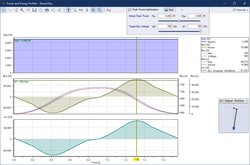
Users can manually adjust Pps, Ppr, Vt0 and Vt1. However,
clicking on the Optimize Peak Power 'Start' button runs the process
that finds the best possible combination of Pp and Vt to minimize
the Mains Supply Peak Power [Pmax].
In the solution below, Pp = 4,465W and
Vt = 780Vdc.
Sometimes there are 2 solution types - the 1st is the lowest
Pmax, and the 2nd may have a higher Pmax that is constant over the
entire cycle. In this example, there is only one solution, Minimum
Pmax with constant power over the entire cycle.
This is a common solution in the servo press industry, using a
lot of bus storage, combined with managing the infeed supply power
to reduce and smooth the mains supply.
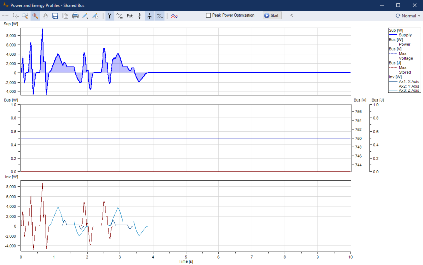
A 3 Axis Gantry robot application is not typical to use with
Peak Power Optimization. However it is included here to illustrate
what is possible using the Peak Power Optimization feature.
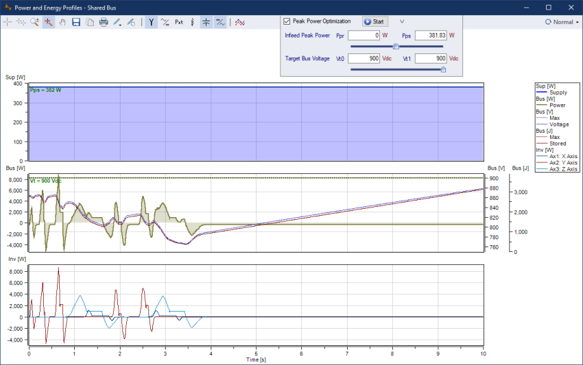
In the 3 Axis Gantry robot example below, the Infeed Module
Rated Peak Bus Power = 30kW, and requires 9kW of peak power from
the Mains Supply. This is a very "peaky" application, as are most
pick and place applications. The Infeed Module has
V0 = V1 = 750Vdc, with 0J of energy stored on
the DC Bus.
Using Peak Power Optimization with V0=750Vdc and V1=900Vdc with
15mF on the DC Bus provides 1900J of energy storage. This results
in the Mains Supply peak power reduced by 87% to 700W.
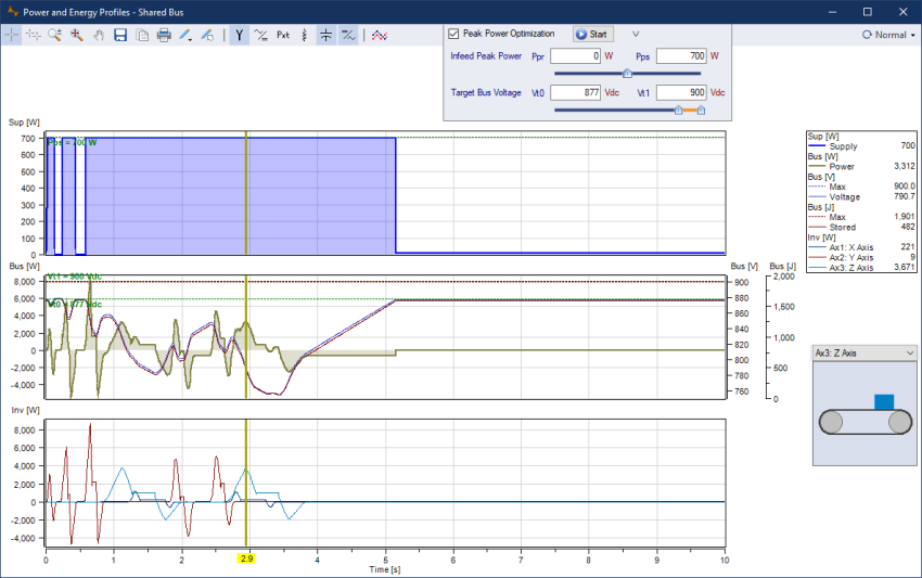
Increasing the DC Bus capacitance further to 30mF providing
3700J of energy storage, the supply peak power can be limited to
just 382W, resulting in a const power draw from the Mains Supply.
The supply peak power is deceased 96% from 9kW to just 382W. In
effect, the 382W continuous power is merely the losses in the
system.
Related topics
 Vertical Press with
Continuous Supply Power
Vertical Press with
Continuous Supply Power