Rotary Motor
|
|
|
Torque profile for each move segment |
||||||||||||||||||||||||
|
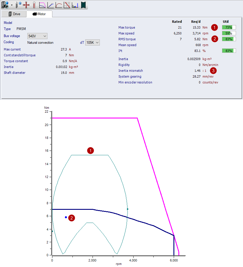
RMS Torque The RMS torque is a thermal equivalent to be compared with a motor continuous thermal limit.
For simplicity, the above example does not include jerk.
In actuality, the acceleration and deceleration torque ramps are
each subdivided into many samples, allowing a more precise RMS
torque calculation for S-curved and CAM profiles. |
|||||||||||||||||||||||||
|
Inertia Mismatch Calculations Inertia mismatch (IM) is the ratio of system load Inertia to motor rotor inertia
Basic Concepts Rules of thumb for speed vs stability:
As the inertia mismatch decreases, the motor rotor inertia
becomes a larger portion of the system load. A lower inertia
mismatch offers improved stability, but comes at a cost.
Holding the load inertia and motion profiles constant, a motor with
increased rotor inertia, increases the system inertia. Hence,
for the same motion profile, additional torque and power is
required to accelerate and decelerate the increased system
inertia. The increased torque and power requirements may lead
to upsizing system components including the inverter, bleeder,
infeed module, etc. |
|||||||||||||||||||||||||