Overload Monitoring |
Overload monitoring models are used to ensure Infeed Modules, Bleeder Modules, Energy Storage Modules (ESM), Inverters and Motors do not overheat when in an overload condition (application value > continuous rated value) for a prolonged duration. The continuous power and rms current and torque values cover most conditions. However, if the cycle time is very long, the rms and average values can be minimized. The Overload Monitoring accounts for this situation, by applying an exponentially weighted time factor to the overload value (utilization factor, U).
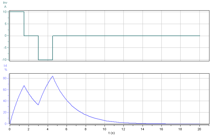
 Sample Scenario: Inverter Ixt
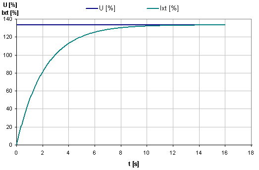
Therefore, the inverter utilization, U = 10A / 7.5A x 100% = 133%. Since U > 100%, the inverter is in an overload condition. Worth noting is that 10A is only 50% of the inverter's maximum output current. As shown in the chart below, in this particular case, the Ixt value peaks at 84%, so the inverter will operate below its maximum rated internal temperature.
Next, consider the same scenario as above, except that the accel and decel durations increase from 1.5s to 3s. In this new scenario, the inverter Ixt value exceeds 100% reaching a maximum value of 107%. This implies that the inverter will overheat. Either the inverter must be upsized or the application requirements must be reduced. The main point here is that the inverter is still operating at 133% of its continuous current rating (utilization, U = 133%). The difference is the duration of the overload condition.
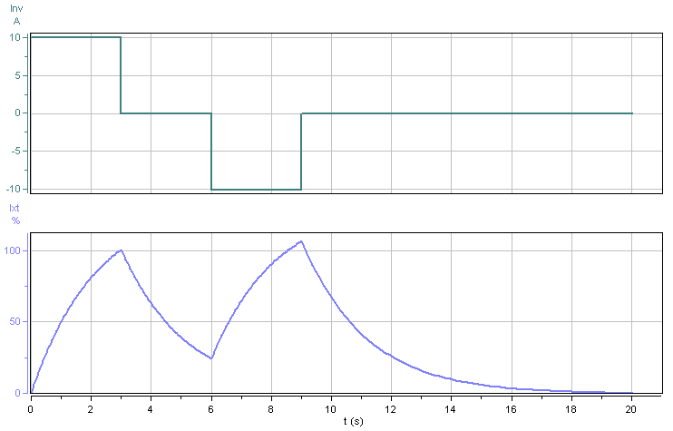
The actual Ixt model for the above scenario is shown below. With U = 133%, the Ixt value reaches 100% at 2.9s, which is consistent with the results above.
 Formulae
Infeed Pxt
Exponential Tiered
Formulae
Infeed Pxt
Exponential Tiered
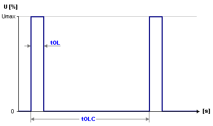
The Exponential Tiered overload model is based on the Umax, Overload time (tOL) and Overload cycle time (tOLC) variables and uses an exponential decay model. Up to 3 different Pxt parameter sets can be defined. Only one Pxt parameter set is used depending on the Umax of the application, where the maximum application overload must be <= Umax. If only one Pxt parameter set is specified then Pxt this parameter set is always used. For this reason, Pxt0 should always be defined for the Inverter rated maximum power Pmax.
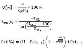
| Symbol | Description | Units |
|---|---|---|
| U | Utilization overload at sample [n] | % |
| P | Application power at sample [n] | W |
| PN | Rated continuous power | W |
| tOL | Overload time | s |
| tPU | Thermic constant | s |
| kLF |
Supply Voltage, Ambient Temperature & Elevation Load
Factors |
1 |
Fast Slow
The Fast Slow overload model is based on the Nominal Power, [PN], time constant [tc] and the exponent [x]. The program applies up to 3 Pxt models in parallel, and uses the higher value at each time sample in the cycle.
For a longer time constant, tc> 100s, usually one of the 3 Pxt models will have PN= Pcont, rated continuous power. Note that [PN] can be any value >0, when combined with [x] and [tc] that best fits the thermal modelling requirements for one of the key sub-components in the Infeed stage. Common values used by some manufacturers for a Fast Slow model are:
Fast: PN= 2*Pcont, x=1 and
tc= 5
Slow: PN= Pcont, x=1 and
tc= 400
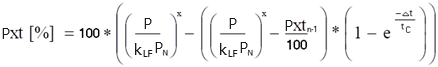
| Symbol | Description | Units |
|---|---|---|
| P | Application power at sample [n] | W |
| PN | Nominal power | W |
| Pxtn-1 | Pxt value at previous sample [n-1] | % |
| x | Exponent (1 or 2) | 1 |
| tc | Time constant | s |
| kv |
Supply Voltage Load Factor |
1 |
| VACN | Main supply nominal voltage | Vac |
| VDCN | DC Bus nominal voltage | Vdc |
| kLF |
Supply Voltage, Ambient Temperature & Elevation Load
Factors |
1 |
Inverter Ixt
Exponential Tiered
The Exponential Tiered overload model is based on the Umax, Overload time (tOL) and Overload cycle time (tOLC) variables and uses an exponential decay model. Up to 3 different Ixt parameter sets can be defined. Only one Ixt parameter set is used depending on the Umax of the application, where the maximum application overload must be <= Umax. If only one Ixt parameter set is specified then Ixt this parameter set is always used. For this reason, Ixt0 should always be defined for the Inverter rated maximum current Imax.
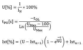
| Symbol | Description | Units |
|---|---|---|
| U | Utilization overload at sample [n] | % |
| I | Application current at sample [n] | A |
| IN | Rated continuous current | A |
| tOL | Overload time | s |
| tPU | Thermic constant | s |
| k |
De-rating factor k = kLF * kfHz |
1 |
| kLF | Ambient temperature and elevation Load Factor | 1 |
| kfHz |
Low Speed factor (0-5Hz) k=2/3 at standstill (0Hz) |
1 |
Fast Slow
The Fast Slow overload model is based on the Nominal Current, [IN], time constant [tc] and the exponent [x]. The program applies up to 3 Ixt models in parallel, and uses the higher value at each time sample in the cycle.
For a longer time constant, tc> 100s, usually one of the 3 Ixt models will have IN= Icont, which is the PWM frequency dependant rated continuous current. Note that [IN] can be any value >0, when combined with [x] and [tc] that best fits the thermal modelling requirements for one of the key sub-components in the inverter. Common values used by some manufacturers for a Fast Slow model are:
Fast: IN= 2*Icont, x=2 and
tc= 5
Slow: IN= Icont, x=2 and
tc= 400
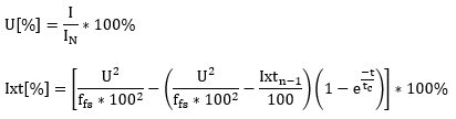
| Symbol | Description | Units |
|---|---|---|
| I | Application current at sample [n] | A |
| IN | Nominal current | A |
| Ixtn-1 | Ixt value at previous sample [n-1] | % |
| x | Exponent (1 or 2) | 1 |
| tc | Time constant | s |
| k |
De-rating factor k = kLF * kFrml |
1 |
| kLF | Ambient temperature and elevation Load Factor | 1 |
| kFrml |
Derating Formula that can be a function of fHz = Inverter Output Frequency [Hz] If kFrml is empty, then kFrml= 2/3 (fHz = 0Hz) kFrml= 1 (fHz <> 0Hz) |
1 |
Bleeder Bxt
Bxt model is applied to Bleeders
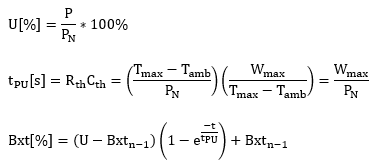
| Symbol | Description | Units |
|---|---|---|
| P | Application power at sample [n] | W |
| PN | Rated continuous power | W |
| tPU | Thermic constant | s |
| Rth | Thermal resistance to ambient | K/W |
| Cth | Thermal capacitance | J/K |
| Tmax | Resistor maximum temperature | oC |
| Tamb | Ambient temperature | oC |
| Wmax | Max energy dissipation | J |
| Bxtn-1 | Bxt value at previous sample [n-1] | % |
Energy Storage Module I2t
The ESM I2t model is applied to Energy Storage Modules (ESMs)
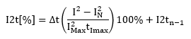
| Symbol | Description | Units |
|---|---|---|
| I | Application current at sample [n] | A |
| IN | Rated continuous current | A |
| IMax | Rated maximum current | A |
| tmax | Duration at rated max current | s |
| I2tn-1 | I2t value at previous sample [n-1] | % |
Motor I2t
Motor I2t model is applied to Motors
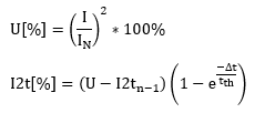
| Symbol | Description | Units |
|---|---|---|
| I | Application current at sample [n] | A |
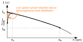
| IN | Rated continuous current at rated torque and speed [nN] | A |
| In | Rated continuous current at torque and speed | A |
| I0 | Rated continuous current at standstill | A |
| ∆t | Sample time | s |
| tth | Thermal time constant | s |
| I2tn-1 | I2t value at previous sample [n-1] | % |
| nh |
Speed at homogeneous heat distribution at |
rpm |