Main Form |
The Main form is the center of SERVOsoft. Navigate your project using the treeview on the left, or use the EasySize Wizard on the right of the form. The main menu and toolbar at the top of the form provide project type functions such as open and save projects, create Print Reports, Manage Axes, open System Check, open the Bill of Material (BOM), set Max-Stop mode, etc.
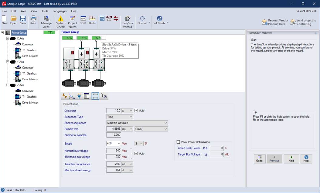
The Power View allows you to set the Cycle Time, and specify how Shorter Sequences are handled. For shared bus systems, you can also specify the mains supply, and there is an option to override the nominal and threshold bus voltages.
"Sample Time" and "Number of Samples" are directly related. "Sample Time" specifies the time between power samples for the power flow calculations through all the electrical components including the Infeed, Bleeder and Energy Storage Modules, as well as the DC bus. The "Number of Samples" is the "Cycle Time" divided by the "Sample Time".
A Power Group is a group of 1 or more axes/slots connected to the same Mains Supply. Each Power Group can be in a stand alone or shared bus configuration. The number of Power Groups can be set in the EasySize Wizard on the Main form, or using the Manage Axes form, where Power Groups can also be moved, copied, deleted, etc.
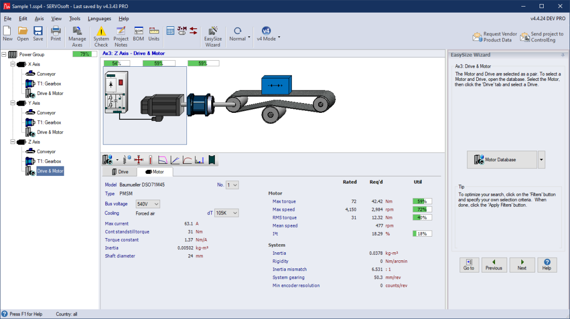
The Axis View shows the complete drive line, from the drive, motor, brake, one or more transformations including couplings and gearboxes, ending with the mechanism at the right. Each stage of the drive line can be selected directly from the treeview on the left, or using the wizard at the right of the form. In the axis view, you can also click directly on the component stage to navigate to it. When a stage is selected, the appropriate component toolbar is avaliable in the middle of the form. In the case when the drive motor is selected, the drive motor toolbar allows users to open the drive and motor database for product selection, set drive and motor limits, enable the motor brake, set the environment conditions, open the drive motor performance chart, open the motor torque vs current chart, etc.
The utilization bars in the Power View provide a quick high level view of each axis. The Axis View provides the utilization of each component in the axis drive line. Utilization bars show a percentage value indicating how much of a component's rated value is utilized. If a rated value or user defined limit is exceeded, the utilization bar is red; otherwise, the utilization bar is green. In the image below, the Z axis motor is operating at 59% because the motor is using 59% of its rated maximum torque. Hover over the utilization bar and a tooltip appears with a high level breakdown as shown below.
Main Form: Power View with mouse hovering over the Axis 3 (Z Axis)
Utilization Bar
Main Form: Axis 3 (Z Axis) View with Drive & Motor stage
selected