News
Company News
SERVOsoft® News
- SEW EURODRIVE publishes product data for new PxG® economy line
Jun 16, 2026 - SERVOsoft v4.7.110 Released!
May 17, 2026 - SERVOsoft v4.7 Released!
Feb 16, 2026 - WITTENSTEIN cyber motor
publishes servo drive
solutions in SERVOsoft
Sep 29, 2025 - SERVOsoft Cloud Released!
May 23, 2025 - Energy Storage Modules
Tutorial
Jan 12, 2025
SERVOsoft News
SERVOsoft® v4.6 Released!
Aug 1, 2024
See highlights of the v4.5 release on Apr 28, 2023. For all release details, see the Revision Log.
This release covers the gamut including a new mechanism, significant improvements to the power/electrical model, as well as improvements to most components such as gearboxes, motors, rack & pinions, ball screws, ESMs, infeed modules, drives, thermal models, etc.
Linear Belt Actuators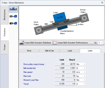
Working closely with our project partner, Macron Dynamics, the newly added Linear Belt Actuator feature includes all the sizing considerations including:
- Belt Max Tensile Load
- Cart Mass
- Mass Distance from Cart
- Max Load Limit
- Moment Load Max Limit
- Force vs Speed performance chart
Macron Dynamics products in database:
- 35x MSA Series Linear Belt Actuators
- 25x MPG Series Planetary Gearboxes
Also added Mechanisms in Parallel (n>1) support for
- Linear Belt Actuator
- Conveyor
Spooler Hanging Load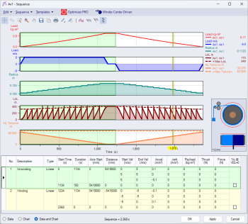
The Winder Spooler (aka Winch) is extended with a Hanging Load. A dynamic model, considering each layer wrap of material and the changing hanging load of material.
Note in the image to the right, when the chart crosshairs are selected, the material is displayed in two views - side view showing the radius of material (blue) wrt full (red) and below the top view, showing where the material is located across the width of the roller.
The Spooler Hanging Load is available for both the Winder Center & Winder Surface Driven mechanisms.
Sequence Chart Rated Profiles with Margin Limits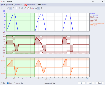
When the Rated profile is displayed in the Sequence chart, the rated profile is shaded in the "margin" area underneath. Eg. If the Motor Peak Torque Margin is 30%, then the motor Tmax rated profile is drawn with a shaded region 70-100% of Tmax as shown. And if the motor torque operates within the margin region, it is highlighted in red as shown in the Motor Torque chart (maroon) in the 2nd and 3rd moves and in the Infeed Power chart (orange) in the 3rd move.
Added Profile Type Sinusoidal2 and Move Rules 1/5 & 1/10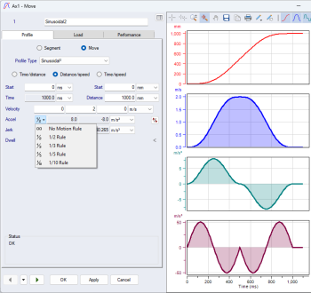
Added new profile type "Sinusoidal²" as shown.
Added the following motion rules for all profile types
- 1/5 [20/60/20]
- 1/10 [10/80/10]
The 1/2 & 1/3 rule buttons in v4.5 and earlier are changed in v4.6 to a drop-down list to accommodate all rules.
The 1/5 and 1/10 rules are especially helpful in applications where the move is defined as Time/Distance and the max velocity is calculated while maintaining the motion rule.
Motor I2t Low-Speed De-rating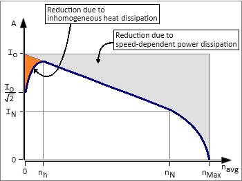
Added motor I2t low-speed de-rating when the motor's electrical frequency <= 5Hz. The I2t model de-rates the rated torque starting at 0rpm with Io/SQRT(2), using an exponential model up to 5Hz.
The inhomogeneous heat dissipation region, shown in orange, is defined from 0rpm up to [nh] where [nh] is calculated using 5Hz and the motor number of pole pairs.
The same approach is used for Linear Motors except using the pole width [m].
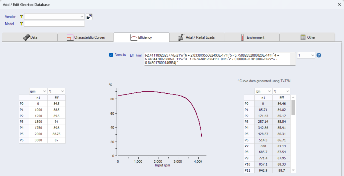
Gearbox Torque Based Efficiency using Efficiency Formula
When the Formula [Eff_Frml] checkbox is enabled, the Gearbox efficiency allows for a formula that can be a function of Input Speed [n] and Output Torque [T], allowing for more accurate efficiency modelling under different torque loads. The standard Efficiency vs Speed curve (on the left) remains for backwards compatibility and when Formula [Eff_Frml] is not used.
Energy Storage Modules: Added 'Droop Curve' Control Mode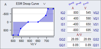
Added 'Droop Curve' in addition to the existing 'Voltage Threshold' control. The Droop Curve configurable parameters appear in a drop-down added at the top of the Power vs Time form, as shown.
The Droop Curve defines the control characteristics for the ESM defining the relationship between the DC Bus Voltage [Vz] and Current [Iz].
Worth noting in the database, changed Capacitance field name from [C] to [Cc] to clarify capacitance on the ESM capacitor side. Then added a new field [Cz], for capacitance on the DC Bus, allowing for ESMs that have capacitance on the DC Bus side.
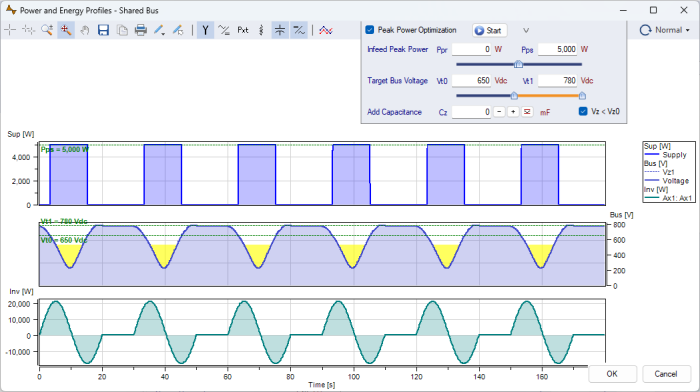
Enhanced DC Bus Modelling where [Vz] Dips in Normal Mode
In Normal mode, when Supply Peak Power Optimization is enabled and also the Allow Vz < Vz0 checkbox is selected, the DC Bus Voltage [Vz] is allowed to drop below the Nominal Bus Voltage [Vz0]. Applies in all cases, with or without an ESM and/or KB on the DC Bus.
But why is [Vz] allowed to drop only when Supply Peak Power Optimization is enabled? Because something must "give". When Supply Peak Power Optimization is enabled, the peak power limit of each Infeed Module "holds", and any additional power comes from the DC Bus, and then [Vz] decreases. When Supply Peak Power is disabled, then [Vz] "holds" at [Vz0] and then any additional power comes from the Supply via the Infeed Module.
Note: Supply Peak Power Optimization is a PRO version feature.
Below are 3 charts - Supply Power, Bus Voltage and Inverter Power.
- 1st chart: Supply power is limited to 5kW
- 2nd chart: Bus Voltage profile "fills" in yellow when Vz < Vz0 where Vz0 = 540Vdc in this example
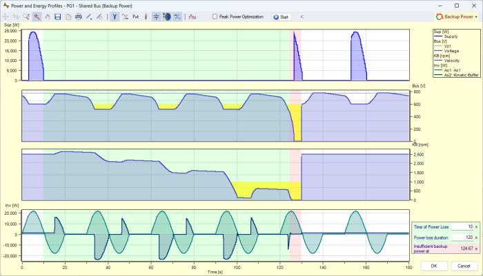
Enhanced DC Bus Modelling where [Vz] Dips in Backup Power Mode
In Backup Power mode, the DC Bus voltage [Vz] is allowed to drop after the ESM and/or KB run out of energy. Previously in v4.5, once the ESM and/or KB ran out of energy, Backup Power mode stopped and did not continue to run down the DC Bus. Now with the added capability, there are 3 tiers of backup power - ESM, KB and then the DC Bus CM bank.
Note this applies if Supply Peak Power Optimization is enabled or disabled since the Mains Supply is gone in Backup Power mode.
Below are 4 charts - Supply Power, Bus Voltage, KB Velocity and Inverter Power.
- 2nd chart: Bus Voltage profile "fills" in yellow when Vz < Vz0 where Vz0 = 600Vdc in this example
- 3rc chart: KB Velocity profile "fills" in yellow when KB Velocity < KB Min Velocity, where
KB Min Velocity = 1,000 rpm in this example.
Optimizer: Suggested Paramaters & Other Enhancements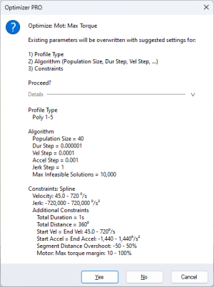
- Now list suggested parameters (shown to the right) before applying them, allowing the user to see the parameters clearly before all the fields are populated.
- Added "Supply Peak Power" & "Supply Cont Power" optimization targets for Single Axis Optimization
- Improved handling of Additional Constraints allowing the Optimizer to work through "tough" Additional Constraints and not "give up" too quickly
- Additional Constraints
- Added Mechanism Utilization Constraint used for Master Axis Optimization
- Added Mechanism Constraints for Max Torque/Force Margin and Max Speed Margin
- Add/Edit Constraints
- Now Pre-fill initial values in the Min/Max textboxes when new Additional Constraint type is selected of type Margin (10-100%) or Utilization (90-100%)
Other New Enhancements
- Database
- Prevent Losing Product Data when by adding 'Database Auto Backup' to capture all product data entered manually into the database using the Add/Edit forms
- Infeed Modules
- Max allowed DC Bus Capacitance (guard against high inrush current)
- Inverter Ixt Thermal Overload Model
- Added Ixt_kFrml for each Ixt0, 1 & 2 in each Inverter PWM Frequency, fs0, 1, 2 & 3
- Ixt_kFrml is applied to the Ixt Fast Slow model, using the Inverter Output Frequency [fHz] and DC Bus Voltage De-rating [Vzdr] variables
- Ixt_kFrml formula can be used at any frequency range.
- All components that support more than 1 in parallel (n>1)
- Increased the max number of components in parallel from 6 to 20
- For more details, see the Help: What's New in v4.6
Database
The SERVOsoft® database continues to grow with frequent updates, and now contains over 150,000+ products! Click here for a summary of the current products in the database.
If you are a vendor and want to add your products to the SERVOsoft® database and/or are interested in the Manufacturer Promotion Version, please contact us.