News
Company News
SERVOsoft® News
- SEW EURODRIVE publishes product data for new PxG® economy line
Jun 16, 2026 - SERVOsoft v4.7.110 Released!
May 17, 2026 - SERVOsoft v4.7 Released!
Feb 16, 2026 - WITTENSTEIN cyber motor
publishes servo drive
solutions in SERVOsoft
Sep 29, 2025 - SERVOsoft Cloud Released!
May 23, 2025 - Energy Storage Modules
Tutorial
Jan 12, 2025
SERVOsoft News
SERVOsoft® v4.6.530 Released
Apr 27, 2025
See highlights of the v4.6 release on Aug 1, 2024. For all release details, see the Revision Log.
This release announces the CAM Driven Rotary Table, along with significant enhancements including Gearbox Shaft Loads % Transmitted Radial & Axial Force, a really clever chart improvement showing the effective working envelope within all the rated values and margins, and tops it off with a list of quality enhancements.
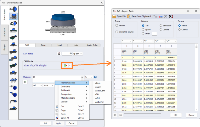
CAM Driven Rotary Table
Added CAM Rotary mechanism that models a CAM Driven Rotary table. The CAM is defined in a table that can be defined manually or imported from another tool. The CAM Efficiency can be defined as a formula based on the CAM & Table angle, speed and max speed.
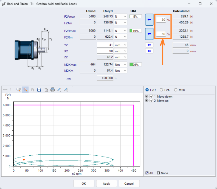
Gearbox Shaft Loads % Transmitted Radial & Axial Force
Now specify how much of the calculated radial and axial load is transmitted to the gearbox output. One scenario this is intended for is the concept of a partially supported load.
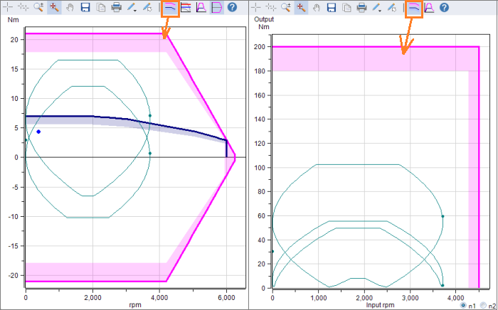
Performance Charts Add Margin Limits: "See" Your Working Envelope
Added "Show Margins" button in the chart toolbar, where the margins are shaded for each rated profile. This allows the user to clearly "see" the working envelope within the user specified margins. Applies to all performance charts including Motor, Drive, Gearbox/Transformation, and Mechanisms.
Below are charts for a Motor (2 Quadrants) and Gearbox.
Linear Actuators Max Tensile Force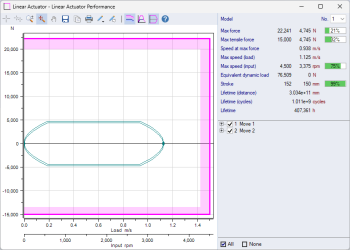
Added [FMaxTensile] column to the Linear Actuators database table to be able to define the Max Tensile Force (max pull force) if it is less than the FMax force. Allows proper support for Linear Actuators where the Pull force is less than the Push force.
In the image to the right, showing Force vs Speed chart with 2 Quadrants, Push & Pull, where:
- FMax = 22,000 N
- FMaxTensile = -15,000 N
Main form Show/Hide Gearbox Input Rated & Application Values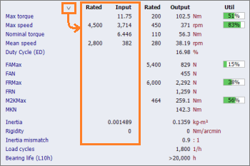
On the Main form, added the option to display the input rated and application values in addition to the output values. Just click the expand arrow to show the input values.
Added Hanging Load to Winders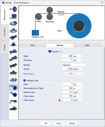
Added Hanging Load without Spooler for both Winder Center & Surface Driven.
In the Sequence form, additional Payload can be added or subtracted to the overall Hanging Load. Consider a a center driven winder with a gripper attached to it. The gripper has its own mass (25 kg), which is a constant hanging load. During the Sequence, the gripper grabs an object (50kg) from a storage area and the winder pulls it up and drops it off at a higher level. Then on the way down, the gripper is empty and the total hanging load is only the gripper mass of 25 kg, but on the way up, the total hanging load is 75kg.
Note: The Spooler with Hanging Load was added in the initial v4.6 release on Aug 1st, 2024.
Sequence form Improved Mechanism Images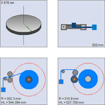
Mechanism images are available for most mechanisms in the Sequence and Power vs Time forms when the chart crosshairs is selected. The purpose is to help visualize the mechanism orientation and how it moves when the crosshairs are moved throughout the motion sequence.
- Rotary & CAM Rotary
- Improved 3D image
- Improved 3D image
- Linear Belt Actuator
- Supports 'Pusher' type
- Supports 'Pusher' type
- Winder Center Driven
- Supports Hanging Load
- Winder Surface Driven
- Supports Hanging Load
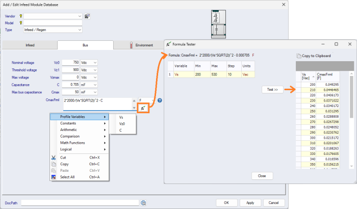
Formula Tester: Infeed [Cmax], Inverter [kFrml], Gearbox [Eff_Frml], Pump [Q, Ql, M, L]
Added the Formula Tester to all product data formulae in the Add/Edit forms including:
- Infeed [Cmax]
- Inverter [kFrml]
- Gearbox [Eff_Frml]
- Pump [Q, Ql, M, L]
The Formula Tester allows for the detailed testing of the formulae for a range of variable values.
For example, the Infeed [Cmax] formula feature was a long time coming, allowing for the vendor to specify more precisely the max allowed DC Bus capacitance based on Supply Voltage [Vs], DC Bus Nominal Voltage [Vz0] and the Infeed/Drive own internal Capacitance [C].
Other New Enhancements
- Sequence
- Increased the max number of chart profiles from 6 to 10
- Import Sequence
- When importing Time vs Velocity or Time vs Velocity & Accel data and Payload, Thrust & Torque/Force is selected, now allow option "Add to Payload" inertia. This can be useful when importing a motor trace and use a negative "Add to Payload" value to remove the motor inertia torque from the imported trace.
- Main form
- Added Transformation Limits
- Added Mechanism Limits
- Conveyor
- Added 'Max force' and 'Max speed' margins
- Linear Belt Actuator Mechanisms
- Added 'Max force' and 'Max speed' margins
- Ball Screw Mechanism
- Added 'Max force' and 'Max speed' margins
- Rack & Pinion Mechanism
- Added 'Max force' margin
- Conveyor
-
Drive Axis Internal Power
- Added ContPower (in addition Exg Output Cont and Regen Cont) since the Cont Power thermal limit is constrained by the total power flowing through the infeed stage
- Added show/hide option for the Output and Regen values which are now hidden by default
- Voltage Units [Vac] or [Vdc]
- Clarify everywhere if the Voltage units are [Vac] or [Vdc], includes all aspects of the program including the Main form, BOM, Print Report, etc.
- STOBER Rack & Gearbox Pinion Sizing Rules
- Added new columns [Fsv0], [Fsv1] & [Fsv2] which is the limiting Max Force based on the rack mounting to the machine
- Fsv0 [N] Max force with 125mm spacing fixing screws and pins at both ends
- Fsv1 [N] Max force with 62.5mm spacing fixing screws and without pins
- Fsv2 [N] Max force with 62.5mm spacing fixing screws and pins at both ends
- Added System Check message when Rack has bore holes and rack data includes Fsv0/1/2 values which are the rated force values based on the rack mounting number and spacing of bolts and pins
- Added new columns [Fsv0], [Fsv1] & [Fsv2] which is the limiting Max Force based on the rack mounting to the machine
- Help
- Added Gearbox Resonance Frequency page
Database
The SERVOsoft® database continues to grow with frequent updates, and now contains over 150,000+ products! Click here for a summary of the current products in the database.
If you are a vendor and want to add your products to the SERVOsoft® database and/or are interested in the Manufacturer Promotion Version, please contact us.